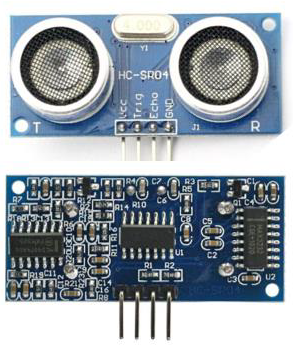
Today, I will share the project where we use 2x Arduino where each Arduino
act as Transmitter to measure a distance using Ultrasonic sensor and
Receiver controlling L98N motor driver.
Two output Motor Driver with Enable pin for both Motor.
Requirement:
1. 2x Arduino
2. 2x MCP2515 CAN module
3. L298N Motor Driver
4. Ultrasonic Sensor
5. 12V battery
6. Download NewPing, SPI and mcp2515 into Arduino.
Instruction:
1. Connect Arduino Nano to Ultrasonic sensor.
2. Connect Arduino Nano to MCP2515(1) through SPI connection.
3. Connect MCP2515(1) with MCP2515(2) using CAN-H and CAN-L wire.
4. Connect MCP2515(2) to Arduino Uno through SPI connection.
5. Connect Arduino Uno with Motor L298N.
Code:
 |
| Ultrasonic Sesnor |
 | ||||||
| L298N Motor Driver |
Requirement:
1. 2x Arduino
2. 2x MCP2515 CAN module
3. L298N Motor Driver
4. Ultrasonic Sensor
5. 12V battery
6. Download NewPing, SPI and mcp2515 into Arduino.
Instruction:
1. Connect Arduino Nano to Ultrasonic sensor.
2. Connect Arduino Nano to MCP2515(1) through SPI connection.
3. Connect MCP2515(1) with MCP2515(2) using CAN-H and CAN-L wire.
4. Connect MCP2515(2) to Arduino Uno through SPI connection.
5. Connect Arduino Uno with Motor L298N.
Code:
Transmitter:
#include
<NewPing.h>
#include
<SPI.h> //Library for
using SPI Communication
#include
<mcp2515.h> //Library for
using CAN Communication
#define
trigPin 3 //Sensor Echo pin connected to Arduino pin 3
#define
echoPin 5 //Sensor Trip pin connected to Arduino pin 5
#define
MAX_DISTANCE 350 // Maximum distance we want to ping for (in centimeters).
Maximum sensor distance is rated at 400-500cm.
struct
can_frame canMsg;
MCP2515
mcp2515(10); //Set the pin number
where SPI CS is connected (10 by default)
NewPing
sonar(trigPin, echoPin, MAX_DISTANCE); // NewPing setup of pins and maximum
distance.
float
duration, distance;
void
setup()
{
while (!Serial);
Serial.begin(9600);
SPI.begin(); //Begins SPI communication
mcp2515.reset();
mcp2515.setBitrate(CAN_500KBPS,MCP_8MHZ);
//Sets CAN at speed 500KBPS and Clock 8MHz
mcp2515.setNormalMode();
}
void
loop()
{
duration = sonar.ping();
distance = (duration / 2) * 0.0343;
int h = duration; //Gets duration
int t = distance; //Gets distance
//Serial.print("Distance = ");
//Serial.print(distance); // Distance will be
0 when out of set max range.
//Serial.println(" cm");
canMsg.can_id
= 0x035; //CAN id as
0x036
canMsg.can_dlc = 8; //CAN data length as 8
canMsg.data[0] = h; //Update humidity value in [0]
canMsg.data[1] = t; //Update temperature value in
[1]
canMsg.data[2] = 0x00; //Rest all with 0
canMsg.data[3] = 0x00;
canMsg.data[4] = 0x00;
canMsg.data[5] = 0x00;
canMsg.data[6] = 0x00;
canMsg.data[7] = 0x00;
mcp2515.sendMessage(&canMsg); //Sends the CAN message
delay(1000);
}
Receiver:
#include
<SPI.h> //Library for
using SPI Communication
#include
<mcp2515.h> //Library for
using CAN Communication
struct
can_frame canMsg;
MCP2515
mcp2515(10); // SPI CS
Pin 10
#define
OUR_LED 5
// Motor
A connections
int enA =
9;
int in1 =
8;
int in2 =
7;
// Motor
B connections
int enB =
3;
int in3 =
5;
int in4 =
4;
void
setup() {
SPI.begin(); //Begins SPI
communication
Serial.begin(9600); //Begins Serial Communication
at 9600 baudrate
mcp2515.reset();
mcp2515.setBitrate(CAN_500KBPS,MCP_8MHZ);
//Sets CAN at speed 500KBPS and Clock 8MHz
mcp2515.setNormalMode(); //Sets CAN at normal mode
// Set all the motor control pins to outputs
pinMode(enA, OUTPUT);
pinMode(enB, OUTPUT);
pinMode(in1, OUTPUT);
pinMode(in2, OUTPUT);
pinMode(in3, OUTPUT);
pinMode(in4, OUTPUT);
// Turn ON motors - Initial state
digitalWrite(in1, HIGH); //motor A
digitalWrite(in2, LOW); //motor A
digitalWrite(in3, HIGH); //motor B
digitalWrite(in4, LOW); //motor B
}
void
loop() {
directionControl();
delay(1000);
}
void
directionControl() {
// Set motors to maximum speed
// For PWM maximum possible values are 0 to
255
analogWrite(enA, 255);
analogWrite(enB, 255);
if (mcp2515.readMessage(&canMsg) ==
MCP2515::ERROR_OK) // To receive data (Poll Read)
{
int x = canMsg.data[0];
int y = canMsg.data[1];
Serial.print("Data from ID: 0x");
Serial.print(canMsg.can_id, HEX);
Serial.print(" ");
Serial.print("DLC : ");
Serial.print(canMsg.can_dlc);
Serial.print(" ");
Serial.print("DATA : ");
Serial.print(canMsg.data[0]);
Serial.print(" ");
Serial.print(canMsg.data[1]);
Serial.print(" ");
Serial.print(canMsg.data[2]);
Serial.print(" ");
Serial.print(canMsg.data[3]);
Serial.print(" ");
Serial.print(canMsg.data[4]);
Serial.print(" ");
Serial.print(canMsg.data[5]);
Serial.print(" ");
Serial.print(canMsg.data[6]);
Serial.print(" ");
Serial.print(canMsg.data[7]);
Serial.print("\n");
Serial.print("Duration = ");
Serial.print(x);
Serial.print("% ");
Serial.print("Distance = ");
Serial.print(y);
Serial.println("cm ");
if (canMsg.data[1] >= 17){
// Turn ON motors - Initial state
digitalWrite(in1, HIGH);
digitalWrite(in2, LOW);
digitalWrite(in3, HIGH);
digitalWrite(in4, LOW);
}
else
// Turn off motors
digitalWrite(in1, LOW);
digitalWrite(in2, LOW);
digitalWrite(in3, LOW);
digitalWrite(in4, LOW);
}
}

Comments
Post a Comment